

Blog
LiFePO4 Charging & BMS Guide 2026: CC/CV, Balancing & Protection

TL;DR: A LiFePO4 battery is charged with a constant-current / constant-voltage (CC-CV) profile that ends at a fixed absorption voltage (14.6 V for a 12.8 V pack, 29.2 V for 25.6 V, 58.4 V for 51.2 V). The BMS does not charge the battery — it senses every cell, protects against over/under-voltage and over-temperature, balances cells, and communicates status to the inverter. Most “charging problems” are actually BMS protection trips or a voltage-window mismatch with the charger/inverter, not cell failure. This guide explains the charging profile, balancing methods, mandatory protections, and why a BMS cuts off — from the perspective of a factory like CMX Battery.
1. How LiFePO4 Charging Actually Works (CC-CV)
Unlike lead-acid, which is often trickle-floated indefinitely, LiFePO4 (LFP) follows a constant-current / constant-voltage (CC-CV) profile:
- Constant current (CC / bulk) — the charger pushes a fixed current (e.g., 0.2C–0.5C) while cell voltage rises.
- Constant voltage (CV / absorption) — once pack voltage reaches the absorption setpoint, the charger holds voltage and current tapers naturally as cells fill.
- Termination — charging stops (or drops to a zero/near-zero maintenance current) when current falls below a threshold (commonly 0.02C–0.05C) or a timer expires. There is no float stage in the lead-acid sense; LFP should not be held at absorption voltage indefinitely.
The single number that matters most is the absorption (charge) voltage. For LFP the per-cell value is about 3.65 V, which scales to 14.6 V for a 4-series (12.8 V nominal) pack, 29.2 V for 8-series (25.6 V), and 58.4 V for 16-series (51.2 V). Charge the pack above this and you stress the cells; charge well below it and you leave capacity on the table.
CMX 48100-Ho1 BMS — 51.2 V (16S) factory protection setpoints
These are the out-of-the-box defaults on the CMX 48100-Ho1 BMS (16S / 100 A / 100 Ah, 51.2 V nominal, product-acceptance spec A0, 2023-03-12). Every value is adjustable through the host configuration tool.
| Protection | Trip threshold | Release / recovery | Delay |
|---|---|---|---|
| Cell over-voltage | 3.650 V/cell (alarm 3.600 V) | 3.400 V/cell | 3 s |
| Cell under-voltage | 2.500 V/cell (alarm 2.700 V) | 3.100 V/cell | 3 s |
| Pack over-voltage | 58.2 V | 54.0 V | — |
| Pack under-voltage | 40.0 V | 48.0 V | — |
| Charge over-current (L1 / L2) | 115 A / 130 A | auto after 10 min (3 retries then lock) | 3 s / 0.5 s |
| Discharge over-current (L1 / L2) | 115 A / 130 A | auto after 1 min (3 retries then lock) | 3 s / 0.5 s |
| Short circuit | 400 A ±100 A | — | 450 µs |
| Charge over-temperature | 56 °C | 50 °C | — |
| Discharge over-temperature | 62 °C | 55 °C | — |
| Charge low-temperature (cutoff) | 0 °C | 3 °C | — |
| Discharge low-temperature | −20 °C | −15 °C | — |
| MOSFET over-temperature | 110 °C | 80 °C | — |
| Cell voltage imbalance | 800 mV | 500 mV | — |
Beyond protection, the same BMS provides SOC/SOH estimation (SOC averaged ±5%), passive cell balancing from 3.450 V/cell at a 30 mV window (68 mA), RS485 (9600 bps) to the host/FSU and CAN (500 kbps) to the inverter, and supports up to 16 modules in parallel. Cell and MOS temperatures are sampled on 10 kΩ NTCs (±2 °C); the pack operates from −40 °C to 60 °C. Per-cell thresholds apply to every CMX LiFePO4 platform — a 12.8 V (4S) or 25.6 V (8S) pack uses the same 3.650 V/cell ceiling and 2.500 V/cell floor, scaled to its series count. Figures are for reference; confirm against the latest shipping specification.
2. Charge Voltage by System Voltage
| Pack nominal | Series count | Absorption (charge) | Recommended float / storage |
|---|---|---|---|
| 12.8 V | 4S | 14.6 V | 13.6–13.8 V (or disconnect) |
| 25.6 V | 8S | 29.2 V | 27.2–27.6 V |
| 51.2 V | 16S | 58.4 V | 54.4–55.2 V |
These are pack-level numbers. A correct charger or inverter with a “LiFePO4” profile already encodes them; the danger is using a lead-acid or user-defined profile with the wrong setpoints. If your inverter/charger only offers “AGM” or “gel”, do not use it — those float at ~13.6–13.8 V and never reach absorption, so the pack never fully charges. For the system-voltage decision behind these numbers, see our 12V vs 24V vs 48V guide.
3. Temperature-Compensated & Cold-Weather Charging
LFP cells must not be charged below 0°C (some chemistries allow down to −10°C with reduced current, but the conservative, widely-accepted limit is 0°C). Charging a cold LFP cell drives lithium plating on the anode, which permanently reduces capacity and can create internal shorts.
- BMS low-temperature charge cutoff — a proper BMS opens the charge MOSFET below its low-temp threshold (commonly 0°C) and re-enables above a hysteresis point.
- Self-heating pads — some packs embed heater films that warm the cells to >0°C before allowing charge; the BMS coordinates this.
- Discharge in cold is far more tolerant (typically down to −20°C), but power is derated as temperature drops.
If your pack “won’t charge in winter,” confirm the cell temperature (not the air temperature) and whether the BMS low-temp lockout is engaged — that is correct, safe behavior, not a fault. Our buying guide covers heated vs non-heated options.
CMX 48100-Ho1 note: the BMS enforces a 0 °C charge cutoff (re-enables at 3 °C hysteresis) and allows discharge down to −20 °C. Unlike some heated packs, this 51.2 V module has no embedded heater film — cold charging is prevented by the BMS opening the charge MOSFET, not by active warming. In sub-zero ambient, plan charging for when cells are above freezing, or provide pack-level warming externally. Verify against the current shipping specification.
4. What a BMS Actually Does: Sense, Protect, Communicate
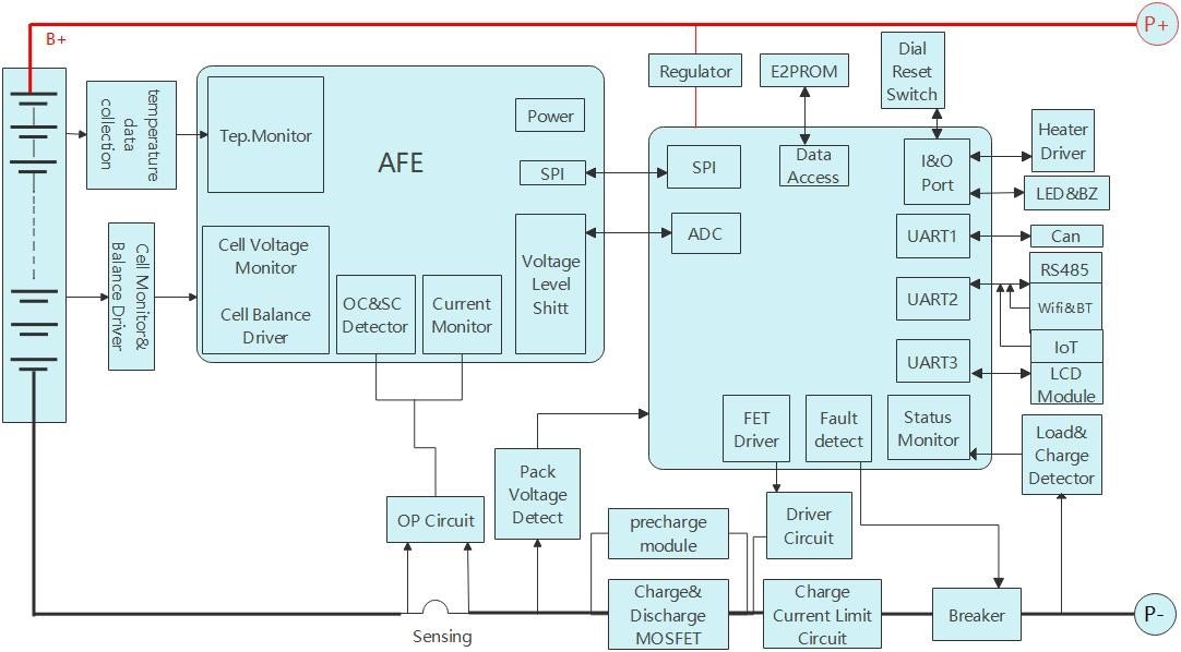
The Battery Management System is the pack’s brain. A minimum BMS does three jobs:
- Sense — measures every cell’s voltage and one or more temperatures, plus pack current via a shunt.
- Protect — opens the charge or discharge MOSFET when a parameter leaves its safe window.
- Communicate — reports state of charge (SOC), voltages, and faults to a display, inverter, or host system over CAN / RS485.
Architecturally a BMS is usually centralized (one board senses all cells via a wiring harness) or distributed (cell-board modules on the pack, a master on the exterior). For wiring and protocol detail, see our CAN vs RS485 guide.
5. Cell Balancing: Active vs Passive
During use, series cells drift apart in state of charge. Balancing equalizes them so no cell hits its limit early.
- Passive balancing — bleeds energy from the highest cell through a resistor (usually during CV/absorption or at rest). Simple, cheap, wastes a little energy as heat. Common in most 12V–48V packs.
- Active balancing — moves charge from high cells to low cells (capacitive or inductive). More efficient, better for large banks and frequent deep cycling, but more complex and costly.
Key point: balancing mainly affects usable capacity at the top end, not safety, when cells are well-matched at assembly. The bigger lever is cell grading before build — matched cells need far less balancing later. Passive is adequate for most stationary LFP; active earns its cost in large, hard-cycled banks. For the “active vs passive” buyer question, the honest answer is “it depends on bank size and cycle depth,” not a universal winner.
6. Mandatory BMS Protections
Any BMS intended for a real application should at minimum provide:
- Over-voltage protection (OVP) — disconnects charge at cell/single-cell limit (typically ~3.65 V).
- Under-voltage protection (UVP) — disconnects load at the discharge floor (typically ~2.5 V/cell). This is what causes “the battery died suddenly.”
- Over-current protection (OCP) — trips on sustained current above rating.
- Short-circuit protection (SCP) — near-instant MOSFET cutoff on a dead short.
- Over-temperature (OTP) / under-temperature (UTP) — blocks charge when too hot or too cold.
These are the protections a responsible buyer should ask a supplier to document. They are also what a certification lab checks (see our UL1973 vs IEC62619 guide).
7. Why Your BMS Keeps Cutting Off Discharge
This is the single most common “fault” report, and it is almost always a protection trip, not a dead battery:
- BMS low-voltage cutoff vs inverter low-voltage shutdown mismatch — if the inverter pulls the pack below the BMS UVP threshold, the BMS opens the discharge MOSFET and everything goes dark. Correct fix: set the inverter’s low-voltage shutdown above the BMS cutoff (see the inverter compatibility guide).
- Inverter inrush / peak power — motor or compressor startup draws 2–5× rated for a moment; if it exceeds BMS OCP, the BMS trips.
- A single weak cell — one cell hits UVP early under load even if pack voltage looks OK; the BMS protects the weakest link.
- Over-temperature — sustained high current in a hot environment trips OTP.
Diagnosis is straightforward: read the BMS fault code (or cell voltages via the app), not just pack voltage. Our troubleshooting guide walks the flow.
8. Communication: How the BMS Talks to the Inverter
Two integration levels exist:
- Open-loop — the inverter sees only pack voltage and current; it does not know individual cell status. The inverter’s own low-voltage setting must be tuned by the user.
- Closed-loop — the BMS sends SOC, current limit, and fault flags to the inverter over CAN/RS485, so the inverter throttles or stops before the BMS has to trip. This is dramatically safer and is the recommended setup for 48V systems.
Closed-loop requires the inverter and BMS to speak the same protocol and same brand handshake. That is why “works with any 48V inverter” is misleading — confirm a tested protocol match. Communication wiring best practices (twisted pairs, separation from HV busbars) are in our wiring guide.
9. Buyer Checklist: Specifying a Charging & BMS Setup
- Confirm the charge profile — your charger/inverter must have a true LiFePO4 CC-CV profile at the correct absorption voltage for your pack’s series count.
- Ask for the protection thresholds in writing — OVP/UVP/OCP/OTP/UTP values and hysteresis.
- Low-temp cutoff — mandatory if the pack sees <0°C; self-heating if you must charge in cold.
- Balancing type — passive is fine for most; specify active for large hard-cycled banks.
- Communication — request closed-loop CAN/RS485 with a named, tested inverter list.
- Monitoring — app or display showing per-cell voltage, not just pack voltage.
10. FAQ
Q1: Can I use a lead-acid charger for LiFePO4?
Only if it has a selectable LiFePO4 (or “LFP”) profile that reaches the correct absorption voltage and then stops — no equalize, no indefinite float. A pure lead-acid “AGM/gel” profile will undercharge the pack because it never reaches absorption. Using the wrong profile is the most common cause of “my LFP never reaches 100%.”
Q2: What absorption voltage should I set for a 48V LFP pack?
About 58.4 V at the pack level (16 cells × 3.65 V). The exact setpoint can vary slightly by cell spec, so follow the cell or pack manufacturer’s data sheet; do not guess. For 12V and 24V equivalents use 14.6 V and 29.2 V respectively.
Q3: Do LiFePO4 batteries need a float charge?
No. Unlike lead-acid, LFP should not be held at absorption voltage continuously. After CV termination the pack is essentially full; a light maintenance voltage (e.g., ~13.6 V for 12V) or simply disconnecting the charger is correct. Perpetual float at 14.6 V accelerates degradation.
Q4: Why does my BMS keep cutting off discharge?
Usually a protection trip: the inverter pulled the pack below the BMS under-voltage cutoff, a startup inrush exceeded over-current protection, one weak cell hit its limit early, or over-temperature tripped. Set the inverter’s low-voltage shutdown above the BMS cutoff and check per-cell voltages, not just pack voltage. Detail in our troubleshooting guide.
Q5: What is the difference between active and passive balancing?
Passive bleeds energy from the highest cell through a resistor (simple, cheap, slightly wasteful); active moves charge from high to low cells (efficient, better for large hard-cycled banks, more costly). For most stationary 12V–48V LFP, passive is adequate; active pays off in big, deeply-cycled banks.
Q6: Can I charge LiFePO4 below freezing?
Not safely. Charging LFP below 0°C risks lithium plating and permanent damage. A proper BMS blocks charging below its low-temp threshold. If you must charge in cold climates, use a pack with self-heating pads that warm cells above 0°C before allowing charge.
Q7: What BMS protections are mandatory?
At minimum: over-voltage (OVP), under-voltage (UVP), over-current (OCP), short-circuit (SCP), and over/under-temperature (OTP/UTP). These should be documented by the supplier and are part of safety certification testing. Ask for the actual threshold values, not just “protected.”
Q8: What does a BMS actually do — does it charge the battery?
No. The BMS senses cells, protects against unsafe conditions, balances cells, and communicates status. The charger or inverter supplies the charging current and voltage profile. The BMS only opens or closes the charge/discharge path.
Q9: Is closed-loop BMS-to-inverter communication worth it?
For 48V and larger systems, yes. Closed-loop lets the inverter throttle or stop before the BMS has to trip a hard cutoff, which is safer and avoids sudden shutdowns. It requires a tested protocol match between inverter and BMS — confirm a supported model list.
Q10: How do I know if my cells are well-matched before assembly?
A serious factory grades cells by capacity, internal resistance, and self-discharge into narrow bins before build, so they stay balanced in service and need minimal balancing. Ask the supplier for their grading spec and incoming-test data; this matters more for long-term health than the balancing method alone.
Q11: Why does my pack read 100% then drop to 80% quickly?
Likely one of: a weak cell hitting UVP early under load (BMS protects the weakest link), an incorrect inverter low-voltage setting causing early cutoff, or a capacity mismatch. Read per-cell voltages under load; if one cell lags the others, it is the culprit, not “false 100%.”
Q12: How should I store a LiFePO4 battery long-term?
Store at ~30–60% state of charge, in a dry place between roughly 0°C and 35°C, and top up every few months. LFP self-discharge is very low, but a long flat storage near empty can let a weak cell drift. Avoid storing fully charged at high temperature.
Related reading
11. Disclaimer
This article is provided for general informational purposes only and does not constitute professional engineering advice. Specifications, parameters, and process descriptions are based on industry-common practices and CMX Battery’s internal assembly documentation, presented here in generalized form. Actual product specifications, protections, and performance data vary by model and configuration — contact CMX Battery’s engineering team for project-specific technical data sheets and quotations. All trademarks belong to their respective owners. CMX Battery is a brand of EGbatt.
CMX batteries with smart BMS protection
- CMX 51.2V 280-300Ah 15kWh Wall-Mounted LiFePO4 Battery with LCD Display — 51.2 V / 280-300 Ah / 15 kWh
- CMX 51.2V 660Ah LiFePO4 Battery for Mini Forklift and Electric Vehicle — 51.2 V / 660 Ah
- CMX 100kW 215kWh Liquid-Cooled LiFePO4 Battery for Commercial and Industrial Energy Storage — 215 kWh / 100 kW
What the chart of a CC-CV charge looks like
Every description of CC-CV charging says the same thing: constant current until the voltage
ceiling, then constant voltage while the current tapers. Fewer sources show how lopsided the two
halves are in practice. Here is a 16-cell 50 Ah pack charged at 50 A (1C) to a 58.4 V limit and held
there until the current decayed to 1 A:
| Stage | Duration | Share of charge time | Capacity delivered | Share of capacity |
|---|---|---|---|---|
| Constant current (50 A held flat) | 61.1 min | 89% | 50.88 Ah | 98.2% |
| Constant voltage (58.4 V held, current tapering to 1 A) | 7.6 min | 11% | 0.92 Ah | 1.8% |
| Total | 68.7 min | 100% | 51.80 Ah | 100% |
That is the honest answer to “do I need to sit through the whole absorption stage every day?” The
last 11% of the charge time buys under 2% of the capacity. What the constant-voltage stage does buy
is balancing time and a tighter spread across the cells at the top of charge — it is a cell-health
stage, not an amp-hour stage. If your charge window is short, cutting the absorption stage short
costs you far less capacity than most people assume; what it costs you is balancing headroom.
The other half of the picture: when the pack, not the charger, ends the charge
On three of the five packs we logged, the charge never reached the bench’s 58.4 V limit at all.
The highest loaded voltage recorded was 56.6–57.0 V, and then the log shows the terminal voltage
jumping to 66–69 V with the current at zero. (A fourth run was cut short by an operator stop, so it
tells us nothing either way; only one of the five completed a full absorption stage.)
That jump is a signature, and it is worth learning to read. A charger running at constant current
into an open circuit has nowhere to push its current, so the terminal voltage runs up to the
charger’s own output ceiling. A reading of 67 V on a 16-cell pack — three volts per cell above the
absorption voltage — is not the battery reaching 67 V. It is the battery’s BMS having opened the
charge path first.
This matters because the log looks like a completed charge and is not one. Practically:
- A charge that ends this way is a BMS event, not a charger event. Look at cell over-voltage,
over-temperature and balance state, not at your charger settings. - Do not report it as a full CC-CV charge. The absorption stage never happened, so the pack has
not been given its balancing time. - On the discharge side the same signature appears inverted: the terminal voltage collapses to
around 1 V while current is still being drawn. That is the discharge path opening, not the cells
emptying. If your inverter faults at that instant, the inverter is downstream of the cause.
Reading the same signature on the discharge side, in numbers
The discharge step in these tests was configured the conventional way: constant current down to a
40 V pack cutoff, which on sixteen cells is 2.50 V per cell. Not one of the five packs was
ever discharged to that point. Look at where each run actually ended, against the setting the bench
was holding:
| Pack configuration | Discharge current | Cutoff configured | Last valid operating point | Per cell | Short of the setting by |
|---|---|---|---|---|---|
| 16-cell, 50 Ah | 50 A (1.00C) | 40.0 V | 41.81 V | 2.613 V | 1.81 V |
| 16-cell, 200 Ah | 80 A (0.40C) | 40.0 V | 41.45 V | 2.591 V | 1.45 V |
| 16-cell, 230 Ah | 90 A (0.39C) | 40.0 V | 43.34 V | 2.709 V | 3.34 V |
| 16-cell, 200 Ah | 90 A (0.45C) | 40.0 V | 43.65 V | 2.728 V | 3.65 V |
| 16-cell, 100 Ah | 60 A (0.60C) | 40.0 V | 43.90 V | 2.744 V | 3.90 V |
Two details in the raw log make the mechanism unambiguous. First, the last valid record of every
run is still at full discharge current — 49.998 A on the 50 Ah pack, 89.998 A on the 90 A runs.
The pack was not tapering, and it was not tired; it was working normally one sample before the end.
Second, the final record of each run is a single-sample collapse: on the 50 Ah pack the log goes
from 41.81 V at 50 A to 0.86 V at 18 A within one timestamp, and the step’s recorded end condition is
the voltage one. Nothing discharges a cell from 2.61 V to 0.05 V in that instant. Something opened the
discharge path, and the sensing input read the resulting near-zero voltage as “below 40 V”.
That “something” is the pack’s own low-voltage protection, and its threshold sits higher than the
bench’s. Which produces the single most useful operating rule in this whole article:
A capacity test only measures what it was allowed to measure. If the pack’s protection
threshold is above the bench’s cutoff, the bench setting is decoration, and the amp-hour figure you
get is the amp-hours above the protection threshold — not the amp-hours in the cells. In our five
runs that didn’t flatter the numbers: every pack still delivered at or above its nameplate rating
despite being cut off early. But on a pack whose protection is set conservatively, the same mechanism
is how a perfectly healthy battery gets reported as “under-performing”.
Raw measurement data
First-party capacity-test bench results under the plant’s standard procedure. Rates and cutoffs as measured; see the article text for interpretation.
Configured cutoff vs actual end-of-discharge, per cell
| Configuration | Discharge current | Set cutoff | Last valid point | Per cell | Above set | Last valid current | Step end condition |
|---|---|---|---|---|---|---|---|
| 16S 50 Ah | 50 A (1.00C) | 40.0 V | 41.81 V | 2.613 V | 1.81 V | -49.998 A (full) | EndVolt |
| 16S 100 Ah | 60 A (0.60C) | 40.0 V | 43.90 V | 2.744 V | 3.90 V | -59.997 A (full) | EndVolt |
| 16S 200 Ah (Jun) | 90 A (0.45C) | 40.0 V | 43.65 V | 2.728 V | 3.65 V | -89.998 A (full) | EndVolt |
| 16S 200 Ah (Feb) | 80 A (0.40C) | 40.0 V | 41.45 V | 2.591 V | 1.45 V | -80.001 A (full) | EndVolt |
| 16S 230 Ah | 90 A (0.39C) | 40.0 V | 43.34 V | 2.709 V | 3.34 V | -90.002 A (full) | EndVolt |
| 128S 409.6 V 150 Ah | 80 A (0.53C) | (no record) | 346.3 V | 2.706 V | – | full load | (CSV has no config table) |
