

Blog
LiFePO4 Battery Troubleshooting Guide 2026: Symptom to Cause to Fix

TL;DR: Most LiFePO4 “failures” are not cell failures — they are protection trips, voltage-window mismatches, or measurement confusion. The golden rule: read per-cell voltage under load, not just pack voltage on a display, and read the BMS fault code before replacing anything. This guide maps the common symptoms (won’t charge, BMS cutoff, low capacity, wrong voltage, swelling, comms loss, fast self-discharge) to their real causes and fixes, in the same factory perspective we use at CMX Battery.
1. How to Read the Symptoms Correctly
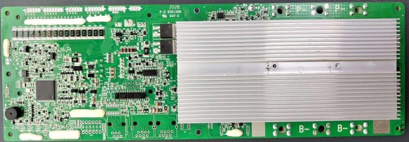
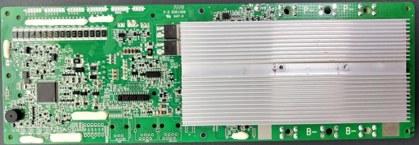
Before touching anything, separate three readings that buyers constantly confuse:
- Pack voltage (resting) — measured with no load, after the surface charge settles (wait 1–2 hours post-charge).
- Pack voltage (loaded) — measured while the inverter/load is drawing; this drops with current and internal resistance.
- Per-cell voltage — the only view that reveals a single weak cell hiding inside a normal-looking pack.
A pack can show a healthy 51.2 V at rest yet collapse under load because one cell is weak. The BMS protects that weakest cell, which is why the whole bank shuts down. Always diagnose at the cell level via the BMS app or a cell-monitor, not the inverter display. For capacity-specific confusion, see our capacity-lower-than-rated guide.
2. “The Battery Won’t Charge”
| Likely cause | How to confirm | Fix |
|---|---|---|
| Wrong charger profile (lead-acid/AGM) | Charger never reaches LFP absorption (14.6/29.2/58.4 V) | Switch to a true LiFePO4 CC-CV profile |
| BMS low-temp lockout | Cell temp < 0°C; charge MOSFET open | Warm cells above 0°C; use self-heating pack if needed |
| BMS fault latched | Fault code present; charge port dead | Clear fault / reset BMS per manual; fix root cause |
| Charger current limit too low | Charger amps < pack acceptance at CV | Use a charger rated for the pack’s C-rate |
Charging detail and correct setpoints are in our charging & BMS guide.
3. “The BMS Cuts Off Under Load”
This is the #1 reported issue and is almost always protection, not death:
- Inverter low-voltage vs BMS cutoff mismatch — the inverter drains the pack below the BMS under-voltage threshold, so the BMS opens the discharge MOSFET. Fix: set inverter low-voltage shutdown above the BMS cutoff (see inverter compatibility).
- Startup inrush — motor/compressor peaks exceed BMS over-current; use soft-start or a pack rated for the peak.
- One weak cell — reaches UVP early; the BMS sacrifices the whole pack to protect it. Find and replace the weak cell/module.
- Over-temperature — sustained high current in heat trips OTP; improve ventilation or derate.
4. “Capacity Is Lower Than Rated”
First, confirm you are measuring usable capacity at the rated C-rate and DoD, not pack voltage. Causes:
- Measurement method error — reading “%” from voltage alone is inaccurate; true capacity needs a controlled discharge. Our capacity guide explains why a 314Ah cell may measure ~200Ah on a bad test.
- A weak cell caps the bank — the weakest cell determines usable Ah; the rest are stranded.
- High C-rate discharge — rated Ah is usually at 0.2C–0.5C; pulling 1C reduces delivered Ah.
- Age / cycle wear — capacity fades with cycles and calendar time; see our cycle-life guide.
5. “Voltage Reads Wrong or Jumps”
- SOC jumps — passive-BMS estimators drift; a full rest + recharge recalibrates. Persistent jumping points to a cell-voltage sensing fault.
- Voltage lower than spec at rest — check the per-cell average: 51.2 V pack ÷ 16 = 3.20 V/cell nominal; a reading far off means a sensing or connection issue, not a spec error.
- Load dip — a drop under load is normal (IR × I); a sudden collapse is the weak-cell signature from §1.
6. “Swelling or Getting Hot”
Stop using the pack. Swelling or abnormal heat is a safety signal:
- Mild case warmth under high C-rate is normal; case >50–60°C or a hot spot is not.
- Visible cell swelling indicates internal gas generation — isolate the pack, move it to a non-combustible location, and contact the supplier. Do not puncture or disassemble.
- Heat + smell — treat as thermal-event risk; evacuate and follow your site’s battery emergency plan.
LFP is far more stable than NMC, but a physically damaged or grossly over-charged cell can still fail. Our certification guide covers the abuse tests that qualify packs for safe deployment.
7. “Monitor / Communication Not Reading”
If your app or display shows no data or wrong data:
- Wiring — CAN/RS485 need correct polarity and twisted pairs, physically separated from HV busbars (detail in our wiring guide).
- Protocol/handshake — closed-loop needs a matched inverter+BMS; a mismatched pair may power on but exchange no valid frames.
- Termination — RS485 buses often need 120Ω end-of-line termination.
- Address/baud — mismatched baud rate or node ID = no comms.
8. “Drains Fast When Nothing Is Running”
High self-discharge or phantom load:
- Genuine cell self-discharge — quality LFP is <1–3% per month; much more suggests a faulty cell or a tiny internal short.
- Always-on loads — inverters, monitors, and DC-DC converters draw standby current; a “0 load” system is rarely truly zero.
- BMS quiescent draw — the BMS itself consumes a small, continuous current; long storage should use the pack’s storage switch or periodic top-up.
9. Diagnostic Toolkit & When to Call the Factory
Minimum tools: a multimeter, the BMS app/cell-monitor, and the inverter’s fault log. A serious installer adds a clamp meter and a controlled load tester. Call the supplier when:
- a cell voltage diverges >50–100 mV from siblings under load;
- swelling, smoke, or heat appears;
- a fault recurs after a legitimate reset;
- capacity is far below spec on a proper discharge test.
10. FAQ
Q1: My battery shows 100% then dies at 80% — is it fake?
Probably not fake — probably a weak cell or a wrong inverter low-voltage setting. The BMS cuts the whole pack when the weakest cell hits under-voltage, stranding the rest. Read per-cell voltage under load; if one lags, that cell is the issue. A proper capacity test (controlled discharge) is the only way to confirm true Ah.
Q2: Why does the BMS cut off right when I start a load?
Startup inrush (motors, compressors) can spike 2–5× rated current and trip over-current protection, or the inverter yanks pack voltage below the BMS under-voltage cutoff. Set inverter low-voltage shutdown above the BMS cutoff and size the pack for the peak, not just the running load.
Q3: Can I keep using a slightly swollen cell?
No. Stop using it. Swelling indicates internal gas generation from over-stress or damage; continuing to cycle it risks thermal failure. Isolate the pack safely and contact the supplier for RMA guidance.
Q4: My monitor shows no data — what do I check first?
Check comms wiring (CAN/RS485 polarity, twisted pairs, separation from HV), baud/address match, and 120Ω RS485 termination. A mismatched inverter+BMS pair often powers on but exchanges no valid frames. See our wiring guide for the physical rules.
Q5: The pack reads 51.2V but won’t run my 48V inverter — why?
Under load the weak cell collapses and pack voltage drops below the inverter’s low-voltage shutdown, so it cuts out even though resting voltage looked fine. Also confirm the inverter’s low-voltage setting sits above the BMS cutoff. Diagnose at the cell level.
Q6: How fast should a healthy LFP self-discharge?
Quality LFP self-discharges <1–3% per month. Much higher suggests a faulty cell, a tiny internal short, or an always-on parasitic load (inverter standby, DC-DC). Rule those out before blaming the cells.
Q7: Is it normal for the case to get warm while charging?
Mild warmth is normal; the pack should not exceed roughly 50–60°C case or develop a hot spot. If it does, reduce current, improve ventilation, or stop and investigate — overheating accelerates degradation and can trip protection.
Q8: What tool do I need to troubleshoot properly?
A multimeter, the BMS app or cell-monitor (per-cell view), and the inverter fault log. For field service, add a clamp meter and a controlled load tester. The key is reading per-cell voltage under load, not pack voltage on a display.
Q9: Why does my SOC jump around?
Voltage-based estimators drift, especially with passive balancing; a full rest followed by a complete charge recalibrates them. Persistent jumping suggests a cell-voltage sensing fault or a weak cell. A current-based (Coulomb-counting) BMS is more stable but still needs periodic full-cycle calibration.
Q10: Can I reset the BMS fault myself?
Many BMS allow a documented reset after the fault condition is cleared, but resetting without fixing the root cause just lets it trip again — and can mask a real safety issue. If the fault recurs, stop and contact the supplier.
Q11: My battery “drains” but nothing is connected — what gives?
Either genuine cell self-discharge (should be tiny) or an always-on parasitic load you forgot (inverter standby, monitor, DC-DC). The BMS itself also draws a small quiescent current. For long storage, use the pack’s storage switch or top up periodically.
Q12: When should I contact the factory instead of DIY?
Contact the supplier when a cell diverges >50–100 mV from siblings under load, when there is swelling/smoke/heat, when a fault recurs after a legitimate reset, or when capacity is far below spec on a proper discharge test. Those are beyond field tweaking.
Related reading
11. Disclaimer
This article is provided for general informational purposes only and does not constitute professional engineering advice. Troubleshooting steps are based on industry-common practices and CMX Battery’s internal service documentation, presented in generalized form. Actual fault behavior and safe procedures vary by model and configuration — always follow the specific product manual and contact CMX Battery’s engineering team for project-specific guidance. All trademarks belong to their respective owners. CMX Battery is a brand of EGbatt.
Before you call it a capacity problem, check the test conditions
“Capacity is lower than rated” is the complaint that most often turns out to be a measurement
problem. The three conditions that move the number, in order of how much they move it: discharge
current, cutoff voltage, and temperature. A pack rated at 0.2C and tested at 1C will look short.
A pack discharged to 3.0 V per cell instead of 2.5 V will look short by roughly 10%.
For scale, here are five 16-cell packs measured on our own production bench, all charged to their
constant-voltage limit and then discharged at a constant current toward a 2.50 V-per-cell cutoff.
Note what the cutoff column does not mean: on all five of these runs the pack’s own protection
opened the discharge path first, and the last valid reading was 2.59–2.74 V per cell. The bench
setting was never reached, so the amp-hours below are the amp-hours above the protection threshold.
| Rated | Current | Measured | Result |
|---|---|---|---|
| 50 Ah | 50 A (1.00C) | 51.5 Ah | 103.0% of rated |
| 100 Ah | 60 A (0.60C) | 117.7 Ah | 117.7% of rated — over-capacity cells (by plant spec) |
| 200 Ah | 90 A (0.45C) | 207.8 Ah | 103.9% of rated |
| 200 Ah | 80 A (0.40C) | 206.6 Ah | 103.3% of rated |
| 230 Ah | 90 A (0.39C) | 235.3 Ah | 102.3% of rated |
None of them came in short. That does not mean short packs do not exist — it means that when one
does, the first question is which conditions the “rated” figure was measured under. And the second
question is which device ended the discharge, because that choice alone can move the number by
several percent without anything being wrong with the cells.
And check whether it is really empty
The second false alarm is a pack that is genuinely flat while its voltage still looks healthy. On
our bench the middle 80% of a 16-cell pack’s discharge covers only about 0.134–0.140 V per cell. By
the time the reading looks meaningfully low, there is almost nothing left:
| Depth of discharge | Cell voltage range across the packs tested |
|---|---|
| 10% | 3.234 – 3.272 V |
| 30% | 3.217 – 3.256 V |
| 50% | 3.196 – 3.229 V |
| 70% | 3.168 – 3.204 V |
| 90% | 3.088 – 3.131 V |
| Final reading before the run ended | 2.591 – 2.744 V |
So a resting 16-cell pack reading in the low 50s is not “nearly flat”. At rest, 3.2 V per cell is
the middle of the range, and the pack will keep supplying current long after the meter starts looking
alarming. If a load cuts out early, look at current and at the BMS, not at voltage.
Raw measurement data
First-party capacity-test bench results under the plant’s standard procedure. Rates and cutoffs as measured; see the article text for interpretation.
Per-cell voltage by depth of discharge (loaded, not open-circuit)
| DOD | 16S 50 Ah | 16S 100 Ah | 16S 200 Ah | 16S 230 Ah |
|---|---|---|---|---|
| 10% | 3.234 | 3.272 | 3.269 | 3.264 |
| 20% | 3.227 | 3.265 | 3.263 | 3.260 |
| 30% | 3.217 | 3.256 | 3.254 | 3.254 |
| 40% | 3.208 | 3.240 | 3.236 | 3.237 |
| 50% | 3.196 | 3.229 | 3.228 | 3.227 |
| 60% | 3.184 | 3.219 | 3.220 | 3.219 |
| 70% | 3.168 | 3.204 | 3.203 | 3.203 |
| 80% | 3.141 | 3.177 | 3.174 | 3.174 |
| 90% | 3.088 | 3.131 | 3.130 | 3.127 |
| Last reading before cutoff | 2.613 | 2.744 | 2.728 | 2.709 |
